


© VinyasiFree Energy does not ExistFree energy is a colloquialism suggesting getting more resultant energy exiting a device per energy expenditure which powers it. Yet, the mathematical concepts which promote and maintain our rebellious belief in "Free Energy" do not exist and neither do the mathematical constructs of electrical reactance. Both are fictions whose theorized existence have weathered our doubts for over a century of experience among electrical engineers encompassing a belief in the practicality of imaginary numbers.
The testimonials of numerous scientists and engineers (who attest to the practicality of their use of imaginary, and complex, enumerations within their calculations) does not prove the existence of imaginary numbers, nor does it prove that they succeed at representing any variety of electrical reactance, free energy or otherwise. And no testimonial has been put forward (by anyone) that imaginary numbers are useless. On the contrary, they are very useful and satisfy the need for using them. This demonstrates that we can "get by" without having to prove how to take the square root of a negative number. No one has a clue how to do that, and nobody expects to find out any time soon...!
Testimonials and demonstrations are no substitute for a well-constructed proof; and neither are arguments. Testimonials are merely opinions, demonstrations are mere shadows of an understanding, and arguments are an attempt to promote a concept and all three are outside the jurisdiction of provability.
A proof demands an understanding which we fail to possess concerning the existence of imaginary numbers. And rationalizations for their usefulness does not substitute for lack of any proof.
Yet, so long as imaginary numbers serve us as a useful tool to temporarily hold an unprovable value, we can continue to use them so long as we never entirely forget that we are assuming the existence of a fantasy for the purposes of practicality.
Without concrete proof for the existence of imaginary numbers (in the world of physicality to which we are born), we will continue to have no physical proof for the existence of free energy, and no physical proof for the existence of electrical reactance since the two are closely related. {By the way, Free Energy is a special case of the more generalized topic of electrical reactance.} All we know is that the math works out based on over a century of "street-wise" expertise.
But the situation gets worse...
Free energy, if it is defined as a special case of electrical reactance, is a fantasy lacking testimonials since we also lack an understanding. The intention of this wiki book is to: stop assuming that free energy does not exist and begin to seek an understanding by talking about it in rational terms which parallel our discussions of electrical reactance.Contents
- 1 Synopsis
- 2 Introduction
- 3 Block Diagram
- 4 Mathematical Consequences
- 5 Utilization of Electrical Reactance
- 6 In Conclusion: What is electricity?
- 7 Alternative Explanation of Current Reversal
- 8 For Further Study
- 9 References
- 10 Translations
Synopsis
There is a conspiracy taking place suppressing free energy;[2] which promotes an irrelevant notion that there's no such thing as a free lunch.
Well, there are discounts all the time. Shoppers love them!
- Buy two; get one free!
- Half-off sale!
- Etc.
That may not be a free lunch, but it sure (as heck) beats paying for the beverages if they're included on Free Beverage Thursday's whenever eating over at Mike's Cafe.
This silly notion (derived from our collective ignorance and misrepresentation of Free Energy) is that you have to, I repeat: HAVE TO, calculate the demand which a load will make upon a supply, and -then- add up all losses due to inefficiencies. This total must be, I repeat: MUST BE, supplied by the power source unless you want your appliance to fail.
That's nice. Yet, it merely describes the REAL POWER side of the equation as if ELECTRICAL REACTANCE does not exist.
It turns out that electrical reactance is extremely, I repeat: EXTREMELY, shy. So much, so, that it doesn't take much voltage supplied by a power source to suppress reactance and prevent the eruption of unlimited oodles of freely available reactive power which, whenever passed through a resistive load: such as a heater element, converts invisible reactance into REAL POWER miraculously convincing us that free energy exists when (in reality) free energy does not exist all by itself.
Free energy is a composition, over time, of the non-suppression of electrical reactance immediately followed by its conversion into usable power.
That's the conspiracy intended to keep all of us ignorant of our options.
It turns out that this "free energy option" involves the reuse of reactance making it look as if (the conversion of reactance into) energy miraculously appeared out of no where when -instead- (what happens, is that) reactance (being lossless) cannot be spent nor lost. It must, thus, accumulate unless converted into a usable format (ie, energy). The accumulation of lossless reactance constitutes its reuse (so to speak) making electrical reactance the easiest available form of renewable energy.
Yet, feeding a circuit too much (ie, conventional expectations of) voltage when that circuit is especially designed to take advantage of this free form of proto-energy (ie, reactance) will guarantee its failure to convince anyone of what I am saying is true.
Also, encouraging a throughput of current (through this type of circuit) giving it an exit for current to pass out of this type of circuit instead of restricting portals of entry or exit to merely one portal exclusively utilized as an inlet for a source of voltage will guarantee suppression of free energy.
So, …
Two criteria will guarantee the suppression of free energy ...
- Feeding a circuit too much voltage, and ...
- Allowing the entry of voltage to develop into a flow of current by providing an exit.
Avoiding bullet points #1 and #2 will not guarantee the production of free energy since you also have to know how to take advantage of their avoidance whenever designing a circuit. But adhering to both points will guarantee its suppression.
Introduction
 Fig. 0 – Triangular waves do not saturate inverted current (relative to voltage). They must escalate the production of negative wattage.The non-existence of Free Energy is not a lie so much as it does not also state that most of electrical engineering dabbles in non-existential reactive power predicated upon imaginary numbers which were invented by Hero of Alexandria to solve intractable problems and avoid the liability of proving their existence in the physical world. In other words, what is the physical manifestation of the solution to...
is a question which has yet to be answered by anyone.
Imaginary answers are not provable since they cannot be measured with physical instruments. They can merely be inferred by the mathematics of complex numbers as possibly existing somewhere in a fictional world often called, "counter-space" wherein everything is backwards (similar to Lewis Carroll's, "Alice in Wonderland" and "Through the Looking Glass") in which elongated distances between the plates of a capacitor in our world of space is shrunken distances in counter-space.[3]
Free energy is not energy, yet it is freely available as a special case of reactive power, namely: the mathematical squaring of an extremely low input of real power (nano watts or pico watts) fed into a circuit which lacks a throughput. This results in the reversal of current traveling backwards towards higher potentials of voltage resulting in the accumulation of a greater difference between those greater potentials and lesser potentials nearby, see: Fig. 0.
Block Diagram
 Fig. 1a – Oscillations of Radiant Energy due to throwing away most of the input and prohibiting the formation of current within this circuit by disallowing an exit which opposes the inlet. For neophyte designers, every inlet should double as an outlet.
 Fig. 1b – Tesla wireless power theory - Electrical Experimenter Feb 1919.
Consider a circuit whose source voltage has merely one of its terminals connected to a circuit (constituting its input) while the other terminal (of this source of voltage) is connected to ground and there is no other ground connected to this style of circuit design (for the purposes of this hypothetical discussion, please see: Fig. 1a).
This configuration (of the terminal connections of a source of voltage feeding a circuit) discourages the manifestation of current which normally flows into a circuit through one portal and flows out through another portal. Instead, a restriction of portals to merely ONE (in addition to severely restricting the input power) encourages breathing without flow, namely: the circuit manifests a standing wave in which the voltage and the current are out of phase by one-half cycle of oscillations. In other words, whenever the peak of voltage bounces off of the periphery of this type of circuit, the peak of current is crossing its imaginary center. During the subsequent half-cycle, the inverse occurs in which the peak of current echoes off of the periphery at the same moment that the peak of voltage crosses the center. This creates an expansion, followed by a contraction, but not in the real world of physicality since the incentive for expansion (voltage potential) and the execution of same (its movement which reflects a flow of current) occur at opposing halves of each cycle of breath (so to speak)!
All of this occurs within the complex field surrounding reactive components.
Although a circular pathway is avoided that would lead from a "source" to a "load" and then, back to the same "source", circular pathways are encouraged within the body of this style of circuitry so long as the various subcircuits are electrically isolated from each other with merely a mutual inductance between them, and/or a single wire of electrical connection without any return path. These electrically isolated, open pathway, subcircuits perform very well if they interconnect via several mutual inductances to make up for their lack of electrical connectivity.
This style of circuit design tends to make it very easy to manifest an inversion of current 180 degrees out of phase with voltage. This inversion of current is oftentimes mistaken for its homologue of the "negation of resistance" which is mathematically equivalent, but not very educational.[4]
A more accurate description would be the negation of reactive voltage divided by impedance, namely:
This leads to another, more traditional, version of Ohm's Law in which Power equals Voltage Squared Divided by Resistance:
.
That conventional version is vague and incorrect in so far as it does not distinguish what is occurring, namely, that: Negative Watts is equal to the Application (the Input) of Real Voltage times its Resultant Output of Reactive Voltage divided by various Impedances (both Real and Imaginary) within a framework of time ...
Granted, this is a more convoluted restatement of Ohm's Law with the distinct advantage of sidestepping the conventional claim of physics in which: "Energy IN equals Energy OUT" by (instead) implying that: "Real Voltage IN cannot equal Reactive Voltage OUT". The resulting reaction of output voltage must be greater than, or less than, input voltage irrespective of thermodynamics. This is in contradistinction to conventional wisdom since (my perspective is that) the input is complex and the output is also complex all the time (a real value plus or minus an imaginary value). In fact, all circuits possess some reactance in proportion to some non-reactance. This is why I deem the traditional presentations of Ohm's Law flawed (in principle) while maintaining a more practical approach for technicians by avoiding a fundamental teaching of how electricity behaves.
Without this fundamental understanding, no one will appreciate Free Energy since they will lack a robust understanding of electricity. I challenge everyone, who desires an understanding of Free Energy, to return to basics and rethink what we've been taught. Ergo, current is a fiction. It is a mathematical shorthand notation replacing something slightly more complicated.
Fig. 1b suggests a similarity to Fig. 1a. Both images possess a singular inlet for power resulting in a periodic variation of potential occurring everywhere, simultaneously, and without any manifestation of conventional current (subject to entropy) that could delay and reduce (through losses) the transmission of power. On the other hand, the reversal of current (in this wikibook's proposal), produces the inversion of losses, namely: an escalation of gain.
This is similar to if, whenever we shop at a market, they pay us to take their groceries instead of charging us! And... Every time we shop, they pay us more than they paid us before while claiming to pay us the same! {The inverse of deprivation.} What a trip! With so much abundance, who needs war?
Mathematical Consequences
A Low Input Power
Lots of Real Power, plus or minus, a modest amount of reactance will guarantee the conventional stability (or, Rule of Thumb) that reactance cannot grow by way of feeding itself from the reactive field surrounding reactive components, such as: inductors and capacitors, resulting from the outcome of the prior cycle of oscillation since excessive real voltage will suppress a runaway self-looping of electrical reactance.
Yet...
Severely restricting the use of real power at the inlet of a circuit's source of energy will encourage the unconventional rule of thumb in which electrical reactance will be almost exclusively nourished by its own feedback irrespective of thermodynamics or the Conservation of Energy – especially since energy plays no significant role, here, since its input is severely limited to be less than a micro watt.In other words, any complex number (enumerating the amplitude of either a wave of voltage or a wave of current) possesses two components: a real number and an imaginary number. The magnitude of the real number regulates the consequence of how the present cycle of oscillation impacts any subsequent cycle. Meanwhile, the imaginary number can create the inversion of current when squared if the self-looping, self-feeding tendency of electrical reactance is not suppressed by any excessive input of real power.
If this complex polynomial...
...is squared...
...then, the result is four products reduced to three (since two results, the cross products of
times
, are similar enough to be grouped together) ...
- The square of the real component,
.
- The cross-product of the real portion times the imaginary portion,
.
- And, the square of the imaginary component,
.
If the real power input of
will grow at an exponential rate. By restricting the inlet of real power (feeding this style of circuitry), there will be an increased likelihood of success in producing radiant power serving as a precursor to free energy. Yet, this is not all that is required to ensure success.
It is also necessary to connect only one terminal of a voltage source to this type of circuit while connecting the other terminal (of the voltage source) to ground and disallow any other ground to be located anywhere else within this type of circuit (in the beginning if you are not yet "skilled in this artistry"). This will ensure that no current forms since it won't have anywhere to drain after scantily leaking into the circuit from the voltage source. This will ensure a radial pattern of oscillations, rather than a circumferential pattern of peaks and troughs, in which the peaks of voltage will bounce off of this circuit's periphery at the same time that the peaks of current will be crossing the virtual center of this type of circuit during each half-cycle with an inverse pattern at the next half-cycle.
In other words, current has been divested of its significance. Only voltage matters, plus: frequency, inductance and capacitance.
Since the inherent tendency of electricity is to make up the difference for any shortcoming, current will form (anyway) despite our best efforts at preventing it. This "last ditch effort" on the part of "nature's tendency" will ensure a reversal of current since that is the only direction we will have allowed for by failing to prevent it.
Ponder this …
If, after taking every precaution to prevent the flow of current, don't you think that the only other option available (to Mother Nature) is for current to flow backwards as if in rebellion to our various restrictions?In the words of actor: Jeff Goldblum's character, portraying a mathematician who specializes in chaos theory in the movie, Jurassic Park (part one): "Life will always find a way to break free of any loss of liberty".
Conservation of Energy is a status symbol confessing allegiance to the herd since it is grounded in physical reality as constituting the ultimate and exclusive verification for any authority while simultaneously ignoring electrical reactance subsisting within the domain of time acting as the trump card (so to speak) giving us the liberty to recycle energy rather than blindly throwing it away (returning it back to its source) after every single use and refusing to pay through the nose for this wasteful method of consuming energy.
Whoever conjured-up this scheme must be a madman!
It sucks!
Voltage Drop
It stands to reason that electrical voltage drop is a mathematical process which cannot be performed upon the imaginary coefficient of a complex polynomial. It may only be performed upon its real number coefficient. This is a consequence of the assumption that voltage drop is the distribution of a real numbered evaluation of voltage across a circuit resulting from simple resistance rather than from electrical reactance.[5] This allows for the accumulation of reactive potential as well as for the accumulation of reactive impedances (both inductive and capacitive). This latter accumulation can occur within the imaginary fields surrounding reactive components only if the distribution of real voltage is kept below useful values amounting to nano watts and pico watts so as to avoid disturbing (suppressing) reactive feedback. This accumulation of reactance serves as feedback for the input of subsequent cycles of oscillation causing reactance to escalate at exponential values. Hence, "free energy" is an incorrect assessment of this peculiar situation. A more rational explanation is to claim "freely available reactance" resulting from an extremely low input of real power.
Convention teaches us that the peaks and troughs of voltage and current may oscillate their amplitudes as they travel around the circumference of a circuit. But there is another possibility in which they may echo their peaks and troughs in diametric opposition to each other during each half of an oscillation effectively creating a standing wave of one-half cycle of displacement between their phases (See, Fig. 1a, above). This will only occur if we discourage or prohibit the formation of current while maximizing the accumulation of the imaginary component of reactive power. At some point, the complex enumeration of the real and imaginary portions of electric power will be squared during our mathematical assessment of the electrodynamic behavior of a circuit. If we keep the input voltage extremely low and suppress the flow of current, then we may succeed at developing more reactance than what conventional wisdom would expect. And when, through simple (thermodynamic) conversion when passed through a resistor, the complex result (of the squaring of a complex value) will have its phases of real voltage realigned with its phases of reactive voltage and with its various impedances (voltage realigned with current possessing a power factor of positive unity,
) and, thus, be able to convert the cross-product of:
Utilization of Electrical Reactance
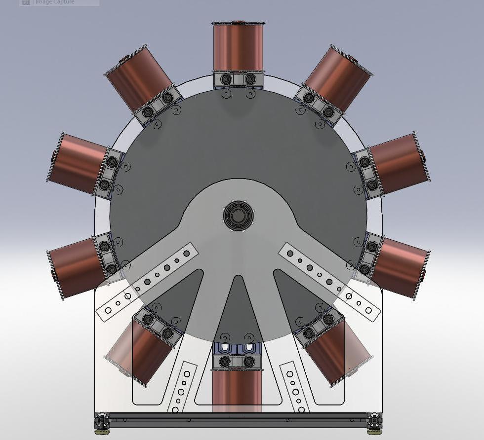
 Fig. 2 is a schematic of a simulation speculated to be the Ammann brothers' Atmospheric Generator.
 Fig. 3 – The runtime simulation of the schematic of Fig. 2 will not achieve overunity without this neon bulb macro from Micro-Cap. There is no conventional source of voltage within this macro, because they are behavioral voltage sources predicated upon logical criteria, i.e.: "if this, then that".
 Fig. 4 – This illustrates the ON/OFF state of the neon bulb, in Fig. 2, and the output of four inductive loads. The escalation of wattage is assisted by an inversion of the polarity of current (relative to voltage) resulting from restricting input and preventing any exit of current.
Freely available reactive power is never useless, except from a thermodynamic viewpoint, until it is converted (via a resistive heating element) to boil water and rotate a steam turbine to generate electrical energy (as one example of conversion) to do away with nuclear power plants and their byproduct of plutonium.
What's Reversal of Current Good For?
Conventional circuits deplete their voltage source by slowly or quickly equalizing the difference in potential between the two terminals of a fixed voltage source, such as: a battery. They do this by moving a conventional direction of current from higher areas of voltage (occurring at one terminal) towards areas of lower voltage (at the opposing terminal). For example, ...
A typical 12-volt auto battery will have around 12.6 volts when fully charged. It only needs to drop down to around 10.5 volts to be considered fully discharged.[6] Unconventional Free Energy circuits, whose current is reversed relative to their polarity of voltage (inducing negative watts as their output power), increase the disparity between the terminals of their reactive components, such as: between the two terminals of a coil of wire. Whatever components exhibit this property, these components become the new "sources" of power for these types of circuits replacing (and over-shadowing) whatever contributions may occur from an external source of power.
Simulated Example
 Schematic for building the simulation of Fig. 2.
→ Was the Hertzian Transmitter the Inspiration for the Ammann Brothers Atmospheric Generator? - Quora
The top-most graph of Fig. 4 traces the output of a node within the Micro-Cap 12 neon bulb macro (depicted in Fig. 3). This node is labeled "NeonBulb.10" (within the graph of Fig. 4), equivalently labeled "Switchchk" (within Fig. 3), which has already risen from its default value of 10 nano volts to a plateau of 10 volts. This indicates that this neon bulb has turned ON into an arcing plasma.
- By the way, if any value closely similar to 10 nano volts were to be traced as the output for this node (within this software macro), then this would indicate a pre-ionizing state preparatory to arcing. This is analogous to what lightning bolts manage to achieve prior to their actual lightning strike. The ionization pathway charts a course preparing for whatever lightning strike may happen to form along this prepared highway.
The second graph (from the top of Fig. 4) traces the output current superimposed over the output voltage of the inductive LOAD as a hyperbolic arch of red (hiding the blue underneath). They are diverging at the far right: the red colored current tracing is escalating upwards in the direction of greater positive amperage while the blue colored voltage is escalating downwards in the direction of greater negative voltage. The third graph is tracing the output voltage of the inductive Barrel Coil whose blue-colored arch swerves upwards at an escalating rate of growth in positively signed voltage while the tracing of the fourth graph is red-colored amperage of the Barrel Coil arching downwards at a similar rate of escalation. The fifth and sixth graphs are tracing the rising output of one inductive side of the Copper Tubing while graphs seven and eight are tracing the output of the other side of the Copper Tubing with the neon bulb in between these two halves of copper.
Disrupting Energy on the Grid
 Fig. 5a – Watch out! Don't position your free energy device within city limits unless it is fully shielded to prevent it from disturbing radio transmission nearby.
 Fig. 5b – Schematic of energy theft from the grid.
I don't think it is entirely accurate that C. Earl Ammann was charged with "stealing energy from the electric utility grid" when he arrived in Washington, D.C. to deliver his EV to the United States Patent Office. He and his brother had demonstrated their EV on the streets of Denver, Colorado, driving it around town, up and down hills, while running it without any batteries.[7] [8]
Instead, I would say that he was "disrupting the grid" since whatever he received from the grid was minimal due to a very weak magnetic coupling existing between the grid and his device. Most of what was "stolen" was lost to the environment benefiting no one.
This arrest is why you and I never heard of him until I ran across a few people on EnergeticForum talking about him. And, now, you know a little of his story.
His theft does not mean he was a fraud. Oh, contrair! It means that the grid got in the way since it was available for having its reactance sucked out of it at an alarming rate. So quickly was this magnetic field extracted, that my simulations (Fig. 5a and Fig. 5b) indicate that a lot of current was being taken from transmission lines located nearby and from the wiring of the homes of their neighbors. Yet, their device would have worked nearly just as efficiently without a grid nearby to suck energy from had they located themselves out in the middle of the ocean or the desert or on some lonely mountain top.
Yet, as my simulation indicates, up-above, in Fig. 2 (which presumes living out in the countryside far away from the electric utility grid), this style of free energy circuitry performs very nicely without any help from energy sources, nearby, getting its reactance from within itself upon its stimulation from external sources, such as: the ambient charge existing in the atmosphere at ground level. This amounts to a mere micro volt which is amply sufficient for stimulating over-reactance in a circuit of appropriate design.
 Oh, pooh!
Since this style of circuitry does not require an external power source, but does require an external catalyst of stimulation, care must be taken to restrict external sources of power to protect those sources from becoming overloaded with huge demands placed upon them arising from this highly reactive type of circuit. Reactance can become a sponge (of inverted current) sucking energy from out of sources of voltage if allowed to do so without limitation.
It is this demand, born of reactance, which broadcasts an inversion of current outwardly towards its environment giving the appearance of making a necessary demand. This imposition is unnecessary. It burdens both the environment and whatever source of power resides there. This is why reactance has been the bane of electrical engineers, for there are two sides of reactance, either: benevolent or demanding. We have to take care to restrict our use of reactance to benefit our appliances without destroying our sources of energy in the course of utilizing them. We do this by becoming mindful of the fact that we no longer need a source of power to fund our devices. All we need is for those sources to catalyze an over-reactance. Once over-reactance takes over (if we let it), it -then- becomes the dominant source for the accumulation of proto-energy (radiant energy; current inversion) which can -then- be converted into real power through mere resistance, alone.
Our sociological "motivation for profit" must be restricted to our motive for leading a productive life without allowing this "motive for profit" to unduly burden anyone or anything. So, I am advocating efficiency and the fair treatment of the consumer in the course of pursuing "free energy". Profit has become the bane of the consumer especially in the wake of inflation in which profit becomes inflated making its pursuit an automatic infringement upon human decency.
The very foundation of our society has been predicated upon the profit motive. Yet, its pursuit has spawned the inflation of our economy making its continued pursuit a violation of human dignity and welfare.
There's no profit to be made from "free energy" if no one can charge us for its consumption.
We avoid being charged for our energy usage by recycling its electrical reactance to such a degree of excessive conservation that a mere factor of 99% reuse (for instance) constitutes a 100 to 1 gain (of output versus input) without any violation of physics.[9]
Conventional vs Non-Conventional Circuits
 Fig. 6a compares two circuits: the output on the bottom graph displays an explosion of gain due to the inversion of current arising from the plasma state of a neon bulb, spark gap.
 Fig. 6b is a more efficient method of flashing a neon bulb ON instead of a conventional method which needlessly wastes input.
→ Lest you think that all of this is due to imperfections of simulation due to round-off error, here are a pair of variations of a conventional circuit which costs a conventionally high drainage made upon some batteries. Yet, the magic does not get initiated there. True, they will contribute their excessive drainage of current, but the magical orchestration will originate (not at the batteries, but) at the neon bulb turning ON (arcing into a plasma) when it reaches its breakdown of resistance at, or above, 90 volts (which is what Micro-Cap simulator sets this threshold at). Then, and only then, will the batteries exceed their prior drainage of nearly 450k amperes to achieve an escalation quickly rising to infinity! This demonstrates the magic of the inversion of current (relative to the phase of voltage) arising, here, exclusively from the neon bulb rather than from any fancy arrangement of electrical components (usually: inductances and capacitances). All of the costs of energy to run this simulated circuit are conforming to conventionally high values expected of them so as to minimize the possibility of no one taking this example, seriously.
The example on the right is more efficient along a style that I frequently employ of using precharged capacitors and/or voltage sources rated at around 1µ volt (a sine wave generator in this example). In this case, this sine source provides a very important frequency of sufficient pitch to accelerate an opportunity for an explosive gain of amplitude to occur without wasting a whole lot of power to facilitate this opportunity. The power is provided by the 10 Farad capacitors (possessing a maximum of 400 milli Ohms, each, of equivalent series resistance) and each are precharged with 100 volts of opposing polarity to coincide with each other in their circular arrangement.
Sometimes, it's important to distinguish between frequency and power and separate them so as to not waste a continuous stream of power to maintain a frequency. This frequency can be very useful in accelerating the time it takes for reactance to explode and yield significant results of amplitude despite the fact that neither formula for electrical reactance (inductive or capacitive) has any factor of kinetic energy, such as: power, amps, or volts, inside of it. Instead, they possess potentialities of power, such as: frequency, inductance, and capacitance per cycle of oscillation defined in terms of angular momentum, or: 2π. Here is another reality to energy which is often overlooked regarding the inherent potential energy already resident within a circuit, namely: its momentum.
Thus, if we focus on a circuit's momentum, rather than focusing on giving the circuit any more energy in addition to whatever it already possesses, then we have an opportunity to manipulate this momentum using the potentialities of: frequency, inductance and capacitance. This does not cost us any more energy than what has already been fed into our circuit.
Think about it …
Isn't this focus on momentum the foundation for anti-gravity levitation? And doesn't electrical reactance make inertia equivalent to gravity? How else do UFO's stay aloft? And make right-angle turns at high speed without slowing down? And suddenly stop without deceleration?This makes me wonder if we have overlooked a very significant perspective in both physics and electrodynamics. Hmmm, ...
No one (usually) thinks of the mass of a coil as possessing potential energy unless that someone was Joseph Newman. Doesn't matter what people thought of him or his ideas of gyroscopic power. Maybe that was his way of describing inductive reactance? What matters is that, at least, he understood the potential power which is inherent within the inductance of a coil and made use of that power even if it could've been done in a more efficient manner. It almost doesn't matter. At least he confronted people with working models even if he may have lied (in his book) on how to build it.
Remember, ...
Input power must step aside and quickly dissipate (using standard thermodynamics) to reduce input and, yet still be able to maintain an excellent output. {I could have used the word: 'conserve' instead of 'reduce', but that might confuse anyone who is brainwashed to think of the laws of physics instead of the economics of conserving our electrical resources.}Negation of current is a powerful factor, within overunity circuits, since negation of watts and the divergence of voltage differences (between two nodes within a circuit) are the result. This leads to the non-saturation of current within inductors (exhibited by triangular waves, or spikes) and a continuous escalation of power at an exponential rate. This rate may not be constant! In other words, a nicely smooth hyperbolic (ascent or descent) away from an oscilloscope's midline of zero may suddenly become a vertical slam into infinite gain!
Similarities to Eric Dollard's LMD Analog Computer
 Fig. 7a compares the pros and cons of two very distinct forms of electrical transmission: the normal type which suffers intense losses versus its converse which gains momentum!
 Fig. 7b – LMD analog computers.
Fig. 6b, up-above, and Fig. 7b (on the right) possess stark similarities to Eric Dollard's Analog Computer in Longitudinal Magneto-Dielectric (LMD) mode since those circuits exhibit their dielectric force (measured in voltage) across their vector of transmission (in series to) their magnetic force of support (in parallel with) their vector of transmission (Fig. 7a). Hence, Eric has managed to create a whole new orientation of transmission existing in the space between a pair of transmission wires in which each whole wire is one of two terminals of transmission while the space between these two terminals is the line of transmission. Since this line of transmission is empty space, this constitutes a line of longitudinal dielectricity while each terminal is a solid composition of magnetizable transverse conductance.
This is, actually, more efficient at transmitting energy since the magnetism of each terminal remains where it is initially located and we do not attempt to move it anywhere. This is a great boon since we have learned, from studying history, that the movement of magnetizable current (in the trans-Atlantic telegraph cable problem of the 1800s) drops off very rapidly over distance making that conventional style of transmission very costly. Instead, we polarize the empty space between a pair of transmission wires with a capacitant charge of voltage (using each magnetizable terminal of conductance as a sort of capacitor plate to this new style of transmission).
Capacitive Negative Resistance Suggests Epicyclic Lunar Rotation
 Fig. 8a – Negative resistance will grow in amplitude (over time) if it is dielectrical, namely: located within capacitors. Negative resistance will shrink in amplitude (over time) if it is inductive or conductive, namely: located within inductors or resistors.
 Fig. 8b – Negative resistance can vary its behavior based on its location.
At 9 minutes and 20 seconds into this YouTube video, we are shown the inside of an electric generator which reminds me of the inside of John Bedini's patented energizer which is different than standard rotary generators.
Here are two more examples of Bedini energizers.
This puts into doubt that the moon is orbiting the Earth since its axis of rotation is not centered within its own (lunar) center of mass but is centered within the Earth's center of mass making it appear as if it is not in orbit around the Earth. Instead, the moon's rotation around the Earth is an extension of the rotation of the Earth's center of mass.
 Fig. 8c – compares cyclic versus epicyclic rotations of standard generator/motor designs versus John Bedini's suggesting lunar rotation around the Earth (in Bedini's case).
The reason why I call this simulated experiment moon (in Fig. 8a and Fig. 8b) is due to an equivalency between John Bedini's design for a very efficient rotary generator and how the moon always keeps the same side facing us throughout its orbit around the Earth. If the moon (representing a coil) had rotated while orbiting the Earth, then it would have been engaging Lenz Law as a consequence of Michael Faraday's Law in which the movement of one magnetic reference frame against another magnetic reference frame produces a counter-opposing force known as: back EMF. This undermines motor, and generator, efficiencies. Since movement is occurring between the magnetic reference frames of both coils (in these simulated examples, of: Fig. 8a and Fig. 8b), this suggests negative resistance is being engaged within the context of inductive and conductive reactances diminishing the amplitude of the waves which are traced in the middle pair and bottom pair of the oscilloscope tracings of Fig. 8a.
But if the moon's spheroidal inductance rotates around, not the center of its own mass, but -rather- the center of the Earth's mass, then it maps an epicyclic path of rotation which does not engage Lenz Law since the surfaces of the inner "red" coils do not move relative to the surface of the outer "black" coil in Fig. 8c. They move together much like a homopolar generator. Since the smaller "red" coils on the inside of Fig. 8c are not rotating relative to the larger and external "black" coil encircling the inner coils, that is one less type of movement to amplify back EMF. Hence, efficiency is improved. This suggests (to me) that negative resistance is engaging dielectric (capacitive) reactance graphed in the top pair of tracings in Fig. 8a.
What does this mean?
Effectively, it means that the moon has no mass and, thus, no angular momentum of its own apart from that imparted to it by the Earth. For if it did possess its own angular momentum, then it would rotate around its own center of mass. Yet, it does not. Instead, it rotates around the Earth's center of mass and will continue to rotate only once around the Sun's center of mass for every cylce of its orbit (once its perturbations of sudden release died down) if the Earth were to suddenly disappear. Mass has the consequence of generating inertia. Without a mass to generate inertia, the moon is "locked" into the Earth's center of mass. Hence, did the Apollo lunar landings actually occur? Could they have occurred? Yes. How?Because this relocation of the moon's center of mass is performed by the moon being composed almost entirely of aluminum, or something similar, which possesses the property of paramagnetism, and if the moon is also largely a vacuous object of a lightweight, but structurally sturdy and honeycombed construction. These stipulations deflect its own center of mass to the Earth which is largely ferromagnetic (due to the Earth's preponderance of iron in its makeup) which has the property of consolidating its own center of mass plus requisition any other object's center of mass to add to its own.
If the moon has any mass (and it's safe to assume that it does, or else the lunar landings would never have occurred ;-), then its mass has been neutralized. Thus, a buoyancy exists which suspends the moon at its height above the Earth instead of our presumption of the mutual gravity between the Earth and the moon acting in conjunction with our assumption of its possession of an orbital momentum as it traces a pathway around the Earth. But under the circumstances, the moon neither possesses orbital momentum nor does it possess angular momentum to rotate. Both actions are taken care of by the Earth's angular momentum and its largely iron composition.
Capacitive negative resistance suggests the epicyclic rotation of our moon since resistance would have to be gainfully negative in order to compensate for the moon's lack of mass with respect to its size. Any other type of resistance would require (demand) a significant mass within the moon to give it sufficient momentum to rotate independent of its orbit around the Earth. Since its orbit is epicyclic, then it cannot have any significant mass. It is a vacuous sphere.
Conversely, this is why the Earth and our Sun are both composed, mostly, of iron. According to the website: TheSurfaceOfTheSun.com – the Sun's hard surface is composed of calcium ferrite underneath its atmospheric plasma of neon and silicon.
How does Free Energy not Violate Conservation?
 A figure skater in a spin uses conservation of angular momentum – decreasing her moment of inertia by drawing in her arms and legs increases her rotational speed.
Definition of Moment of Inertia
For a simple pendulum (an oscillating body/system/circuit), this definition yields a formula for the moment of inertia I in terms of the mass m of the pendulum and its distance r from the pivot point as,Thus, the moment of inertia of the oscillating body (pendulum) depends on both the mass m of a body and its geometry, or shape, as defined by the distance r to the axis of rotation.
How do we accomplish an exponential rise of potential energy without violating the conservation of angular momentum? By separating the mass m of the moment of inertia from its radius (squared)
, we dematerialize the moment of inertia into its electrical equivalencies of: inductance H representing mass m, and capacitance F equaling radius (squared)
dominating the complex number field of the reactance of an electrical component.
When we succeed at reversing current, then there will be no delay: there will be no storage delay within a coil of wire and there will be no storage delay within a capacitor. And there will be no delayed response whenever virtual momentum is stored versus whenever it is released. Coils and capacitors, at this point, become mirrors which merely reflect without storage. Since current is inverted, then there is no delay, and coils and capacitors are receiving the current aspect of their power at the same time that they are exporting the voltage aspect of their power. Hence, a capacitor no longer behaves strictly as a capacitor and a coil of wire no longer strictly behaves as a coil of wire. Each begin to take on the characteristics of the other, but merely in a dynamic manner.
This dynamic condition creates a transformation of the usual dictum of physics, in which: "Energy IN has to equal Energy OUT" becomes true, not for the entire circuit, but for each and every component due to the reversal of current. This reversal of current eliminates any time-delay that Newton's Law of Reaction for every Action would assume.
Furthermore, this reversal of current assumes that what was true in the prior half-cycle of oscillation is no longer true in any subsequent half-cycle due to this separation between voltage and current of one-half cycle of angular displacement (in time; per cycle).
In other words, ...
The result of the previous half-cycle becomes the input for its subsequent half-cycle. And since current is reversed, mass has become separated from radius (squared). This fact, alone, severs any relationship between this process of Free Energy magnification and the conservation of angular momentum across multiple half-cycles.In other words, the conservation of angular momentum is, now, only true for each half-cycle of oscillation while no longer being true across two or more subsequent half-cycles. This is due to the constantly changing features of moment of inertia occurring between any two subsequent half-cycles of oscillation.
Noether's Theorem allows for this discrepancy when it states that the loophole for the Conservation of Energy is whenever time-frames undergo alteration, because conservation is assumed to be true exclusively within the same reference frame (for time); not across two separate and distinctly different time-frames of reference.
The energy conservation law is a consequence of the shift symmetry of time; energy conservation is implied by the empirical fact that the laws of physics do not change with time itself. Philosophically this can be stated as "nothing depends on time per se". In other words, if the physical system is invariant under the continuous symmetry of time translation then its energy (which is the canonical conjugate quantity to time) is conserved. Conversely, systems that are not invariant under shifts in time (e.g. systems with time-dependent potential energy) do not exhibit conservation of energy – unless we consider them to exchange energy with another, an external system so that the theory of the enlarged system becomes time-invariant again.
Editor's note: "nothing depends upon time per se" – Someone went to sleep at the wheel while driving their proverbial electrified vessel! Apparently, physicists could care less about electrodynamics in which electrical reactance depends heavily upon time as its foundation since reactance (ie, "time-dependent potential energy") has no dynamic outside of time. Hence, time-frames (ie, cycles and half-cycles of oscillation) matter a lot!
By the way, ...
This is not quantum mechanics in which "black holes" and "time travel" needs to be invoked for the reversal of light (acting as current reversal) to occur. Instead, simple electrodynamic theory applies, here.It so happens that the reversal of current satisfies this loophole in as much as no two half-cycles of oscillation share the same (equivalent) time-frame. Only each half-cycle of oscillation can be said to be true to its own time-frame servicing its own reference-frame.
And, ...
Electrical reactance formula (used for calculating the inductive and capacitive reactances of inductors and capacitors) bridges the time-frame gap existing between (and across) multiple half-cycles of oscillation since each iteration of calculations of reactance are always true per half-cycle of oscillation, but not true for the next half-cycle since a distinction must be made (in time) between the inductive reactance resulting from one iteration of calculation (from the formula for inductive reactance using the inductance of the magnetic field of an inductor) from the inductance of the prior half-cycle which spawns the inductive reactance (namely: the inductance) for the subsequent half-cycle. Likewise, this is true for calculating capacitive reactance versus the capacitance which spawned it.Ergo, due to the reversal of current, there can no longer be any distinction made between inductance and inductive reactance. Nor can there be any distinction made between capacitance and capacitive reactance, for over time: these distinctions which we used to hold so dear in a static world of make-believe conditions of stability of time-frames is no longer valid outside of any singular half-cycle.
Not until current reforms back into its normal relationship with voltage (in which the phases of oscillatory current are in alignment with the phases of oscillatory voltage) will a whole new value of angular momentum materialize literally out of thin air (out of the reactances of counter-space). Only, then, will conservatives cry, "foul play".
But if we bypass the jurisdiction of the Conservation of Angular Momentum, then no law has been violated!
So, why all the fuss?
By dismantling time, we dismantle conservation. This is what reversal of current manages to accomplish. But only if it is accomplished via analog components; not digital.
True, ...
I've had to use a digital medium of computer simulations to come up with these conclusions and insights. But that's because I trust these multi-thousand dollar simulation softwares are honest in their appraisal of electrodynamics.And they are honest.
Besides giving me an unadulterated view of electrodynamic theory, they also (sometimes) honestly let me "in" on their petty little secrets regarding their policy to tweak whatever their software designer thought was wrong with electrical reality by sometimes "fudging" the software's results. Such as: limiting the current of a diode should it rise above 1kA. This began to bug me until I could no longer tolerate this behavior. This motivated me to peer into the software code (of the simulator in question) to discover a comment made by its designer that: "sometimes, diodes act weird".
To me, that is not acceptable to get a degree in electrical engineering from a prestigious university only to fudge a diode's behavior, because I personally found fault with it!
In Conclusion: What is electricity?
If I rephrase the question as…
What is electrical power, then the correct answer is to say that Ohm's Law is a combination of two components.
The first component of electricity is real voltage which is distributed across space. We will label this type of voltage with the label of:
to signify that this represents Real Voltage.
The second component of electrical power is reactive voltage existing in time. This latter component is divided by one or more various impedances tempting us to simplify this second component of electrical power by way of mathematical substitution in which a singular symbol,
, called: "current", replaces reactive voltage divided by impedance. This latter, more accurate version of the "current" portion of Ohm's Law can be signified by:
.
Hence, Ohm's Law fails to describe power (P, watts) as...
...if we also assume the substitution of
representing the square root of negative one whenever utilized within the field of electrical engineering:
, so as to avoid confusion with the letter
Instead, conventional wisdom allows for their equivalence...
...but fails to distinguish among types of voltages and the implications of expanding our consideration of reactive resistance, namely: impedance
. This mathematical shorthand suggests the illusion that voltage is squared and then it is divided by resistance due to the illusory temptation to assume that there is only one type of voltage rather than two.
Yet, we know that there is electrical reactance within all types of circuits to one degree or another. This awareness is predicated upon the fact that a piece of wire (for example) exhibits inductive reactance along its length and capacitive reactance extending radially outward from its center across its surface (if it's merely bare) plus across its insulation (if it has any on its surface). Thus, a simple flashlight circuit possesses electrical reactance. Yet, this reactance is so minor that we tell ourselves that we may safely ignore it without worrying too much about making some sort of blatant error.
- But this will only work some of the time. We cannot guarantee that this will work most of the time, much less all of the time. And it will certainly never work out very well within the context of my style of orchestrating electrodynamic behavior.
- It is this sort of mental programming that all of us must confront (at one time or another) when we wish to expand our awareness of electricity in general and free energy in particular.
We also know that voltage drop cannot be performed upon imaginary numbers.
This temptation to simplify Ohm's Law makes the job of the technician vastly easier to follow procedures laid down by policies which encourage the monopolistic belief that "there is no such thing as a free lunch".
But if we assume a scarcity of freely available input power, then we are in a much better position to favor over-reactance as a superior source of renewable energy.
Alternative Explanation of Current Reversal
- How to Reverse Current Direction: a single page from the WikiBook, entitled: "Circuit Idea".
For Further Study
Tesla's Magnifying Transmitter
- Audio recording of Eric Dollard reading from his essay, entitled: "Theory of Wireless Power" (1986)
- Radiant Energy is the Precursor to Free Energy (a YouTube video) with parallelisms to Nikola Tesla's Wireless Transmission theory.
- Sending electricity through the Earth (a YouTube video), by Ernst Willem van den Bergh, of Wardenclyffe Research (a YouTube channel).
- Wardenclyffe (YouTube video, with my comments and the OP's responses) ...
Me ...
"Could the reversal of current, relative to the polarity of voltage within his Magnifying Transmitter, be a diagnostic check that his Magnifying Transmitter was succeeding at doing its job of collecting atmospheric electricity? In as much as, this reversal of current would be directing the flow of charges into his device (from the atmosphere) in contradistinction, and in counter-opposition, to conventional devices? Convention dictates that our devices must dissipate their potential to do work since they must follow the dictates of thermodynamics such that their current is in phase with their voltage with little or no separation of their phase relations (at least no separation greater than plus or minus one-quarter cycle of oscillations), and -thus- behave in an entropic manner?"Also to consider, is the fact that his Magnifying Transmitter was orienting its potential in a radial manner, rather than in a circulating manner, since it possessed no return path (it was a monopolar device). Thus, reversal of its current (if this had been the case) would have directed potential inwardly towards itself in the format of a flow of current directed inwardly from the surrounding environment?
"Also, it sounds like a verification that the Ammann brothers' so-called: Atmospheric Generator may have been patterned off of Tesla's Magnifying Transmitter? Now that I've watched this video, this seems more likely than ever before since I've already considered the possibility that they were using one of his patents for their inspiration. But now, it seems very likely!
"In further confirmation...
"It was claimed, by authorities in Washington, D.C., that upon the arrival of C. Earl Ammann with his batteryless EV to demonstrate his technology for the benefit of the U.S. Patent Office, he was promptly arrested on charges of stealing energy from the grid since his demonstration in Denver, Colorado, in August of 1921 (prior to his arrival in Washington) had the distinct side-effect of putting out the power of the grid's customers in the outskirts of downtown Denver (yet, not within downtown Denver, itself). I suspect that he was messing with the phase relations of the grid across the radius of influence of his device (which he has been quoted as saying that it had a ten-mile broadcast radius). So, I'm guessing that he wasn't stealing energy from the grid so much as he was disturbing it throughout its radius of influence while at the same time supplying it with reversed polarity of the flow of energy towards the center of this range of influence at the location of his device. So, at the outskirts of this circle of influence, his device was too weak to have any influence other than that of disturbing the phase angle (or, power factor) of the grid without being strong enough to suck any current through the grid (and from the atmosphere) towards his device at this periphery of its range of influence. Thus, a more accurate assessment would be to claim that he was a domestic terrorist at the outskirts of town (if we would have created that term back then) while also being a Robin Hood of sorts within downtown Denver!"Postscript ...
I have found, with my five years of experience simulating overunity (over-reactive) circuits, that they will usually behave like a glutton and hog energy from a voltage source, but only if the source is provided by way of a hard electrical connection (closed switch in this example), or else by a "soft" connection, such as: a magnetic coupling. {Maybe this is what the Ammann brothers' device made use of? A magnetic coupling to the electric utility grid, nearby, and -thus- rightfully warrant the arrest of C. Earl Ammann as noted above?}If, on the other hand, the source is quickly disconnected, its drainage (by the overly reactive circuit) will be minimized, and this circuit topology will turn to its own reactance to make up the difference, but only if it is isolated from exterior sources, such as: the grid (which pervades the city landscape). So, one could say that sources of energy might get in the way of overunity circuits and, thus, block our attempt at reducing our dependency on those sources of energy (for example: the grid, batteries, solar, geothermal, etc.). Yet, sources of energy are necessary to initiate over-reactance. This is why I have learned to use precharged capacitors, of one micro volt or one milli volt mimicking environmental ambient energy at ground level, to initiate over-reactance and quickly dissipate its precharged energy into the circuit so as to avoid suppressing the evolutionary growth of over-reactance (emanating from this unique form of positive feedback).
OP ...
No, in my experiments I have not seen a reversal of polarity. What happens is that you receive additional current. This is also what you see in lightning. For example 20 MV is just enough to break through 20 m of air, which it does, but then another 20m step is taken, and another etc. (google "stepped leader") This builds up a charges channel and when it connects to ground it discharges violently. This final discharge contains charges collected from the atmosphere surrounding the leader (NOT - as most people assume - from the thunder cloud). As for the Ammann brothers, I have never heard of them, so I can't respond to that.Me ...
I thought arcing spark gaps exhibit the reversal of current (relabeled: negative resistance), yet, mathematically equivalent?On a different note, and getting back to my question ...
I wonder if reversal of current occurs only in the receiver coils? Not in the transmitter?
OP ...
Not sure if I understand what you mean. If you have a 100KHz coil resonating, the current through it reverses 200,000 times per second. In a SGTC, when the spark-gap breaks, it triggers a reversal of current in the primary, starting an oscillation.Me ...
Then, I can assume there is more than one way to accumulate charge other than by reversal of current? And less explosive since, maybe, it is easier to ...2:48
... regulate the magnetic field drawing in charges from the atmosphere when the acceleration of the electrostatic field occurs between the cathode and the anode?OP ...
Yes, I think there are more ways. In fact I am working on one that I hope will work on a much smaller scale.Ether Theory & Gravity
- Tesla's Dynamic Theory of Gravity Quora - Electrical Science
- Nikola Tesla's Dynamic Theory of Gravity (YouTube video)
- Summation of Tesla's Dynamic Theory of Gravity; An excerpt from: Occult Ether Physics, by William R. Lyne.
References
- ↑ How can one show that imaginary numbers really do exist? Argument that Imaginary Numbers Exist. University of Toronto, Mathematics Network
Editor's note: Their only success is proving the concept of imaginary numbers is a valid concept and consistent with the rules of mathematics. They do not prove any analog in the real world which mirrors imaginary numbers in the mathematical world of mental constructs. In fact, they admit that there need not be any analog in the physical world in order to have validity in the world of mathematics. Thus, nothing relevant to a physical proof of imaginary numbers has been offered.
This is important, because it is upon this frail basis that the United States Patent Office refuses to peruse any application for patent which purports to export more energy than it imports.
How can the Patent Office have any authority if it utilizes faulty logic?
Answer...
Obviously, a preference is being exercised which favors convention over reason!- ↑ US patent office reveals number of secret patents
- ↑ Is anyone able to explain Eric Dollard's concepts of space and counter-space? Quora
- ↑ An example of negative resistance simulated in Paul Falstad's circuit simulator (mirrored copy).
- ↑ Jim Phipps answer (on Quora) to: With closed magnetic coupling between primary and secondary, what will improve in a transformer?
- ↑ Everything You Need to Know About the Battery in Your Car or Truck: What Happens When Your Battery's Charge Gets Too Low?, by Bryan Veldboom @Batteries Plus
- ↑ The Error of the Ammann Brothers' Fuel Efficient Vehicles
"While Earl was demonstrating his invention all over the streets of Denver, the power had been cut off in the foothills. In spite of this, when he went to Washington DC shortly afterward to try to obtain a patent on his Cosmo Electric Generator, he found that charges had been filed against him claiming he had a device to steal power from the power lines."
K. H. Isselstein,
Spokane, WA
- ↑ Is it possible to obtain current indirectly from power lines? Skeptics, StackExchange
- ↑ Through power factor correction, using a capacitor in parallel with an inductive load, we can reuse 99% of our electricity in this example. This spawns the appearance of a 100 to 1 gain of output relative to input. Yet, this appearance is a mirage since no law of physics has been violated.
- ↑ Search terms: simulation round off error
- ↑ Erik Anson answers a question on Quora: Is inertia also a force, like gravity, but the opposite?
- ↑ My answer (on Quora) to the question: Has anyone tried to recreate Joseph Newman's perpetual motion machine?
- ↑ Eric Dollard's Analog Computer as a Power Amplifier
- ↑ This text: The Moon's Rotation is read aloud by a narrator (on YouTube), entitled: The Moon's Rotation ♦ By Nikola Tesla ♦ Physics & Mechanics ♦ Audiobook.
- ↑ A few answers (on Quora) to the question of: What would happen if an induced current did not oppose the change that caused it, as in Lenz's law?
Translations
Links to this text can be found here...This may become deleted soon, for its under fire...This is a safe backup copy...This is another safe backup copy...


.jpg)


